 Tel: +86 13342660375
  E-mail:

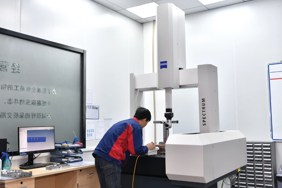
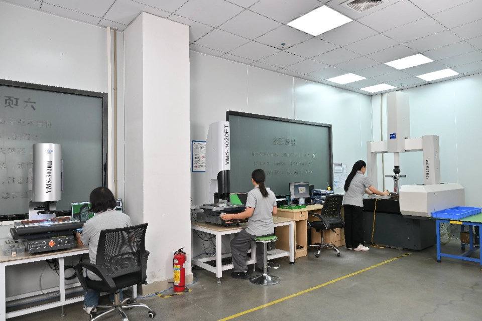


Our quality inspection area is equipped with a German ZEISS coordinate measuring machine for the dimensional verification of precision machined parts, mold components, electrodes, fixtures, and tooling.
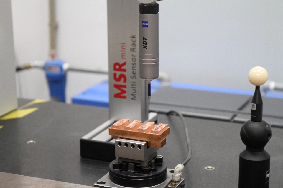
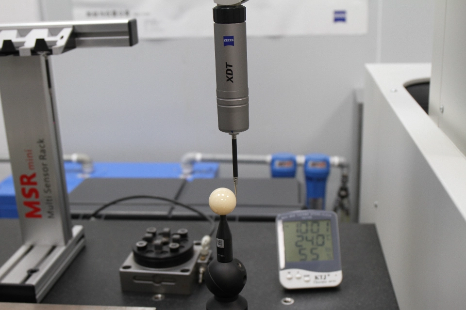
The image shows a ZEISS XDT tactile sensor together with an MSR mini multi-sensor rack. The complete CMM model is not visible, so the equipment is best presented under the general title ZEISS Coordinate Measuring Machine rather than a specific machine model.
The system uses a precision probe to collect measurement points from the component surface and compare the measured geometry with drawing or CAD requirements. It supports the inspection of dimensions, positions, profiles, and geometric tolerances during in-process control and final quality verification.
Key Advantages:
- High-precision dimensional inspection
- Stable geometric measurement
- Automated probe changing
- Detailed inspection reporting
- Reliable production verification
Inspection Capabilities
The ZEISS coordinate measuring machine is used for three-dimensional inspection of components with complex features and close tolerance requirements. The measuring probe contacts selected points on the workpiece while the machine records their spatial coordinates along the X, Y, and Z axes.
The ZEISS XDT sensor visible in the image supports precise measurement in different probing directions. ZEISS states that the sensor uses multi-point acquisition to improve measurement accuracy and reliability compared with conventional single-point triggering.
Typical inspection items include:
- Length, width, height, and thickness
- Hole diameter and center position
- Slot width and spacing
- Flatness and straightness
- Parallelism and perpendicularity
- Roundness and cylindricity
- Coaxiality and concentricity
- Profile and contour deviation
- Electrode feature dimensions
- Position relationships between multiple features
The equipment is suitable for precision steel parts, aluminum components, mold inserts, copper electrodes, tooling components, automation parts, and other workpieces requiring controlled dimensional verification.
Electrode and Mold Component Inspection
The copper component shown in the image is consistent with an EDM electrode or precision mold-related part. Before an electrode is used for die-sinking EDM, its dimensions, feature positions, and profile geometry can be checked on the ZEISS coordinate measuring machine.
This inspection helps verify:
- Electrode length and width
- Rib and slot dimensions
- Feature spacing
- Datum positions
- Machining allowances
- Profile consistency
- Alignment between electrode features
Inspection data can then be used to support electrode offset adjustment, EDM positioning, machining-depth control, and final cavity verification.
Automated Sensor Management
The MSR mini multi-sensor rack visible behind the probe is used to store different styli and probe configurations within the CMM measuring area. The coordinate measuring machine can change stylus systems automatically according to the programmed inspection sequence.
ZEISS describes its Multi Sensor Rack as a passive probe-changing system operated directly by the CMM, allowing different styli to be exchanged without interrupting the programmed measuring process.
This is useful when one component requires:
- Different stylus lengths
- Multiple probe-tip diameters
- Vertical and angled probing
- Access to deep or narrow features
- Measurement from several directions
Automatic probe changing reduces repeated manual setup and supports more consistent inspection of complex components.
Role in Our Quality-Control Process
The ZEISS coordinate measuring machine forms part of our internal machining and inspection workflow. It is used alongside CNC machining, grinding, wire EDM, die-sinking EDM, and other precision manufacturing processes.
A typical inspection workflow may include:
- Drawing and datum review
- Workpiece cleaning and preparation
- Fixture and orientation setup
- Probe qualification
- Automated measurement
- Data comparison with specifications
- Inspection report generation
- Process adjustment when required
Measurement results are shared with engineering, production, EDM, and grinding teams. When dimensional deviations are identified, tool offsets, electrode compensation, fixtures, CNC programs, or finishing allowances can be reviewed before the next production stage.
The ZEISS coordinate measuring machine shown represents part of our factory’s precision quality-control capability. Actual inspection methods are selected according to component geometry, tolerance requirements, datum structure, probe accessibility, and customer drawing specifications.
Contact Information
-
 [email protected]
-
 +86 13342660375Telephone
-
 Address
No. 62, Jinghai East Road, Shatou Community, Chang' an Town, Dongguan City, Guangdong Province, China
Address
No. 62, Jinghai East Road, Shatou Community, Chang' an Town, Dongguan City, Guangdong Province, China
 Schedule a Home Visit
Leave us a Message
Have questions or need assistance? Get in touch with us, and we’ll be happy to help!


