Design review is a product development process whereby a design is developed against its requirements to validate the results of previous activities and to identify issues prior to committing to a milestone in the evaluation
- re-optimized if needed
- Further work.
The final injection Mold spare parts engineering design review, if successful, thus triggers the product launch or product version.
1.Do you use MISUMI specifications or standards? Material: ; Hardness:
2.The ejection distance should be sufficient, and the balanced ejection should be smooth. Is there ejection where the sticking force is large?
3.Whether the ejector hole is guided (chamfering guide/slope guide); whether the surface of the ejector is pulled or worn on one side.
4.Whether there are equal height screws between the ejector plate and the male mold to facilitate the installation of the ejector.
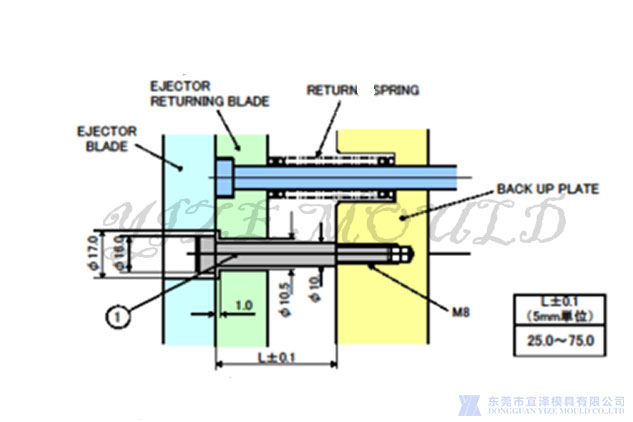
(1)Selection, scope of use: when the spring is used together with the return lever, the Mismi EPB series model is preferred
(2)The length of the shoulder bolt thread must be pre-compressed by the heavy rain spring, which is easy to install the push plate and does not have to bear the spring load
5.Whether the ejector plate is installed with the ejector limit block; whether the double-step ejector die hole is sufficiently avoided, and whether there is any interference.
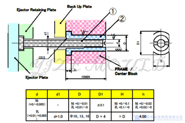
6.It is necessary to split the inserts at the corresponding shaft of Sprue; the workpiece at the E.P sliding fit part needs to be heat treated
Reduce the wear of the ejector rod to the template, and avoid poor ejection caused by the wear of the ejector rod hole of the template.
(1)SPRUE/RINNER LOCK PIN applies when necessary.
(2)Applicable to parts with E.P passing without heat treatment.
(3)The shape and size are as follows.
7.Prevention of burrs at the ejection position on the product: the glue surface above the product should be controlled within 0.05mm.
8.Does the ejector's hanging table interfere? Whether the forming ejector is foolproof and engraved with a number.
9.The position, strength and mileage of the RETURN PIN; whether the ejector guide is properly configured and the movement is smooth.
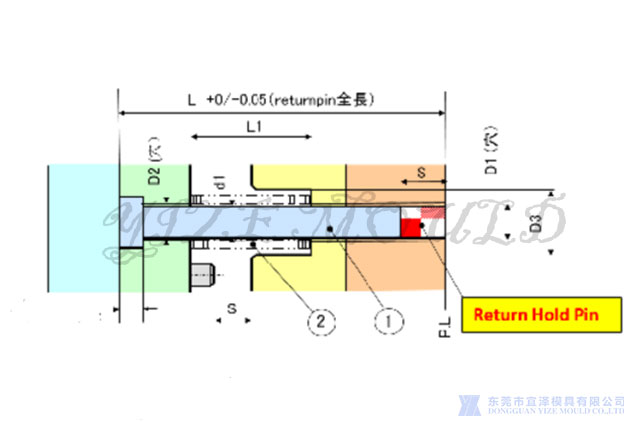
Make sure the putter returns to its original position.
(1)Install at least 4 pieces per mold.
(2)The return lever is generally integrated with the return spring
(3)Not used for positioning between templates.
10.The position and quantity of STOP PIN should be reasonably 5MM in height; the height of the support column must be more than 0.02mm higher than the die foot.
11.Are the number and size of KO holes reasonable? (Fanuc 50Ton or above, 3 KO holes must be designed)
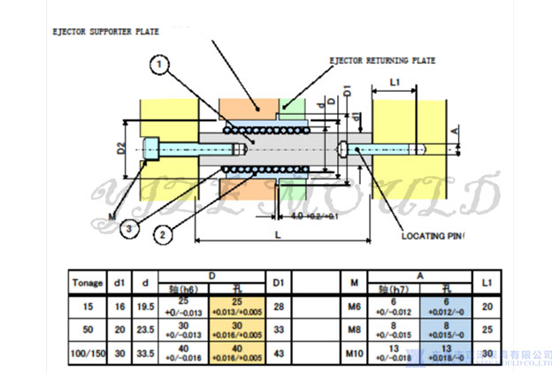
(1)Make the push plate smooth movement.
(2)Determine the location of the E.P.
(3)Diameters can be selected from 3 types: ø16, ø20, and ø30.
(4)Length of the push rod. Choose from the table below according to the size of the mold (SPACER.PLATE). -Applicable when the mold temperature is below 100℃
(5)EJ-PLATE 350mm above a GuIDE PIN6.
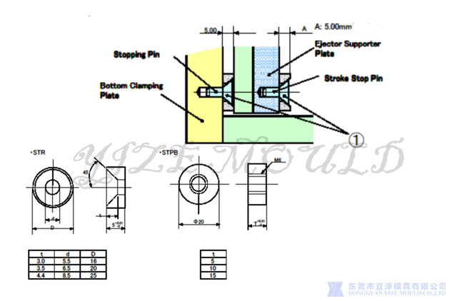
The stop washer is used between the fixed plate of the push plate and the base plate of the movable die to ensure the gap between the two plates and prevent foreign matter from affecting the reset accuracy of the push rod. It is used between the push plate and the support plate to limit the maximum displacement of the ejection action and protect the push rod and spring.
(1)Stop pin reduces bottom clamping plate twist.
(2)Stroke stop pin reduces ejector supporter plate twist.
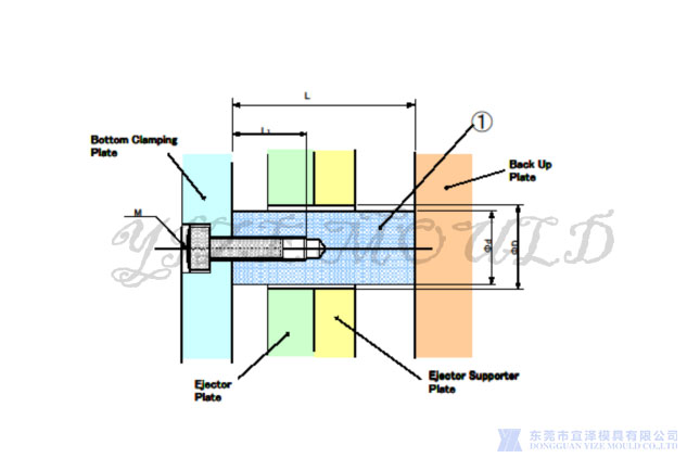
Injection Mold spare parts engineering Support Pillar:
(1). The setting of the Support Pillar should be as close as possible to the place where the injection pressure is under the cavity. If there is enough space, try to choose the large-diameter Support Pillar.
(2). The height L needs to be processed by the Misumi standard SPL model, and the L value is set 0.01~0.02mm higher than the die foot (the initial height is left with a 0.1mm allowance for adjustment)
12.Design principles of ejector rods and holes: the design and installation of ejector rods on vertical and horizontal machines refer to TE design standards
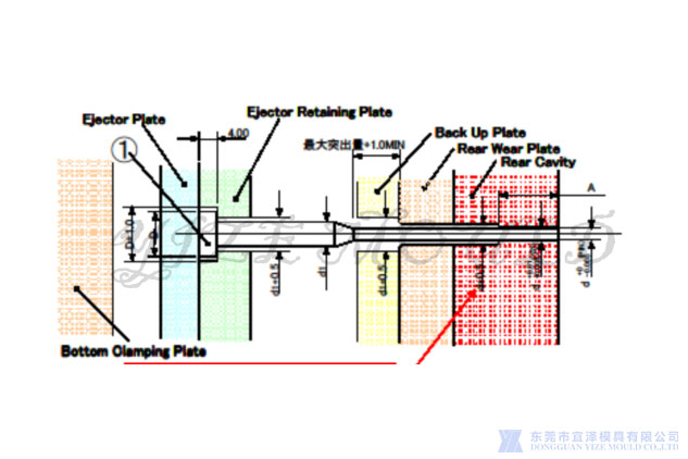
Dome pin Injection Mold spare parts engineering design principles:
(1). The ejector Pin should try to choose a large ejector above ¢2.0, and avoid using the ejector Pin below ¢1.0 for short-cycle molds.
(2) The ejector below ¢2.0 must choose a stepped ejector, and the N value of the ejector should be as long as possible. On the premise that the ejection amount does not interfere, try to enter the mold core as much as possible to strengthen the strength of the ejector.
(3). Special-shaped dome needles must be designed to hang on a platform to prevent fools and prevent rotation
(4) For different types of ejectors, the ejector pusher board needs to be designed as physical foolproof as possible, especially for ejectors with the same diameter and different heights.
13.The design principle of the return sensor of the ejector plate is confirmed; the number of configuration of the return sensor line of the ejector plate: Pcs
14.The ejector dustproof plate needs to be made of PC material. The vertical machine mold does not need to be equipped with the ejector dustproof plate.
Specializing in the production of injection Mold spare parts, plastic mold accessories, die-casting mold accessories, hardware mold accessories and so on. Welcome to picture quotation