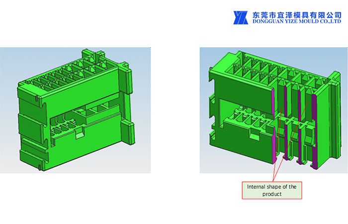
High precision connector injection project of product Pic:
High precision connector injection project of Gate
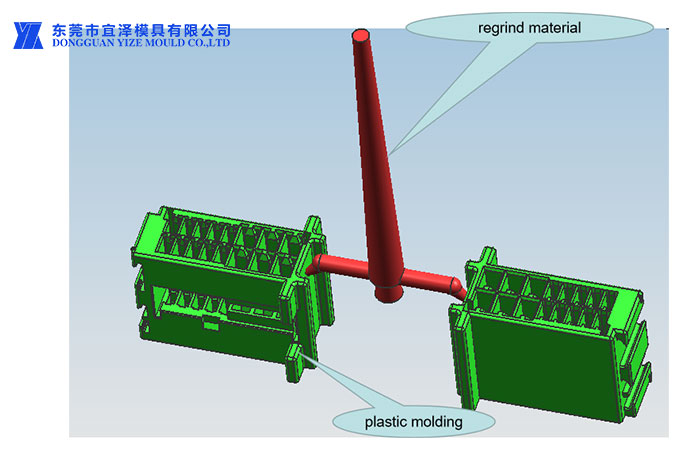
Diagram
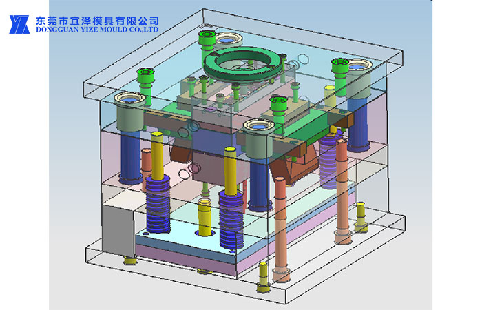
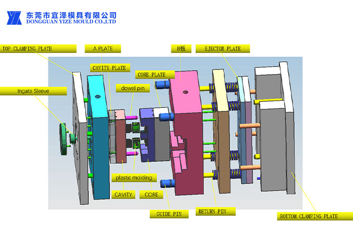
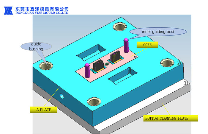
Mold structure diagram
high precision connector injection project of Cavity Schematic
Generally, TOP CLAMPING PLATE and A Plate,it is No. 45 or No. 55 steel, and other parts are alloy steel in CAVITY .
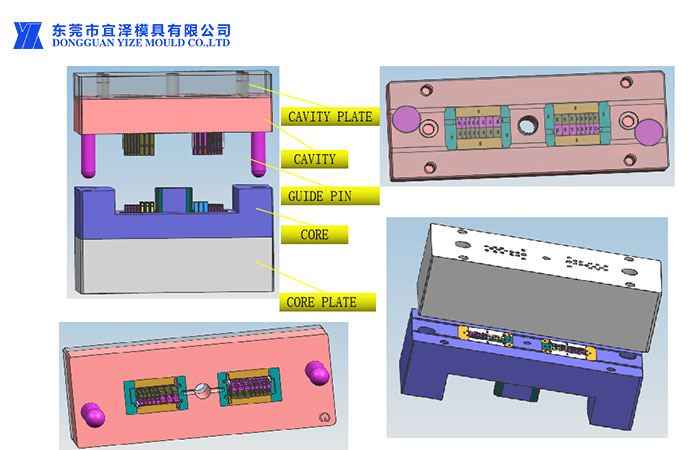
Cavity insert is the core part of the mold,Most of the product accuracy is guaranteed by the machining accuracy of Cavity insert.
A Plate The hole of the intermediate core and the hole of the shovel require high precision,Cavity 、Core、Slide is the most basic guarantee of cooperation.
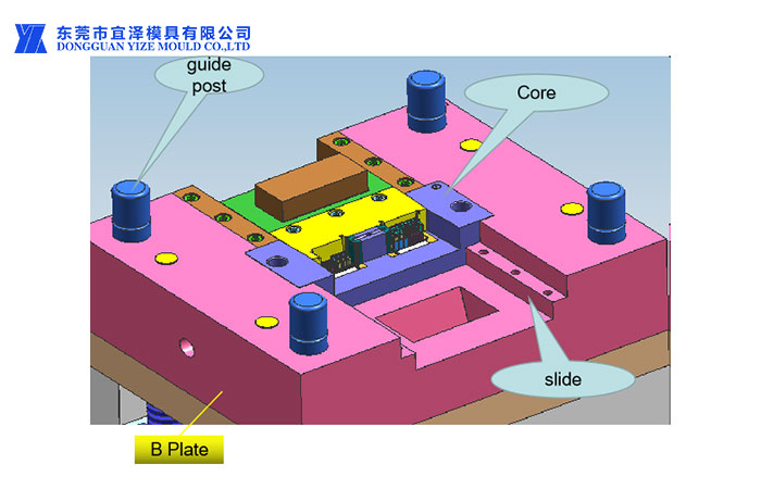
Cavity and core structure and fit
1.The backing plate is mainly used to fix the inserts, inner guide posts and other parts
2.The thickening of the backing plate reduces the processing volume and processing difficulty of the inserts
3.The bottom surface of the thimble via hole must be chamfered
4.All boards are marked with datums to ensure consistent machining and assembly datums and to ensure matching accuracy.
5.The runner processing should be smooth
high precision connector injection project Instructions for processing high precision connector injection project:
1、Core of the right angle is better (within 0.005), and the verticality of all fine holes should be within 0.002
2、inner guiding post holes are processed by +0/+0.002,inner holes are processed by +0/0.005,sprue hole processing by +0/+0.01。Inner guide hole and Insert position of the hole is 0.002 degrees.
3. Leave a margin for the shape during processing. After the line is roughly cut, the CNC will fine-tune the right angle (leave the margin), fine-cut, and finally the shape will be in place (grabbing the hole).
Note: Milling machine, CNC and wire cutting are all processed according to the four sides. The verticality and effective depth of the thread of the milling machine must always be detected, and the water hole should not be too deep (measured with standard screws)。
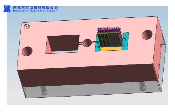
Cavity and Insert
1.Insert AssembleTolerance (cumulative tolerance) is +0/-0.005.
2.mold core All holes on the back can be chamfered to facilitate mold assembly.
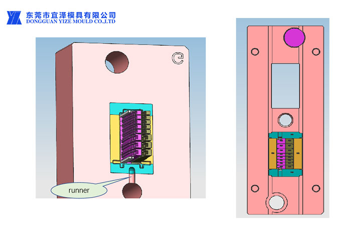
Cavity Assemble the front--B Plate
When processing all positions, the guide post hole is used as the benchmark. The guide post hole is normally processed by the mold frame factory. The middle mold frame must be accurate (+0.005/+0.01).
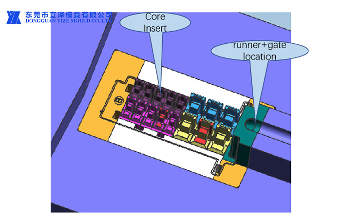
Core and insert
1.gate location The surface should be fine, there should be no carbon deposits, and the runner should be processed by CNC as much as possible to ensure a smooth surface.
2.This type of thimble hole is composed of two grooves on two workpieces. Therefore, the center position of the groove must be accurate; the groove width is +0/0.01, the groove depth is +0/0.005, and the clear angle is within 0.03.
3.The bottom of the thimble hole should be machined with an inclination to facilitate assembly.
4.gate location The surface should be fine, there should be no carbon deposits, and the runner should be processed by CNC as much as possible to ensure a smooth surface。
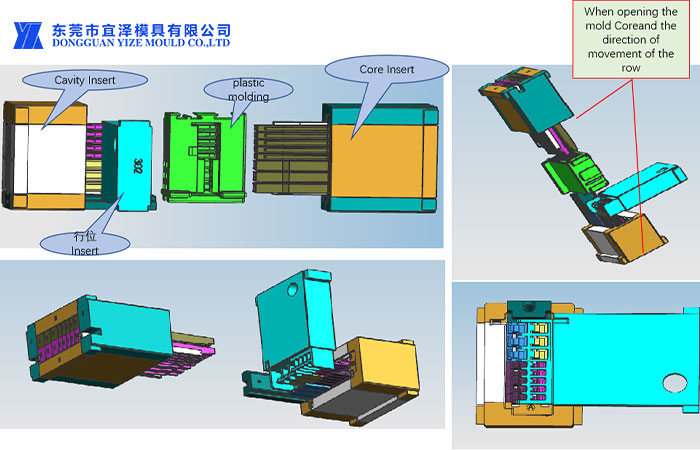
insert Overall coordination diagram
When opening the mold Coreand the direction of movement of the row
Cavity insert and core insert
1.When the mold is closed, the Cavity Insert is first matched with the row insert, and then inserted with the rear mold Insert.
2.When opening the mold Coreand the direction of movement of the row
3.Cavity and Core Insert gate EDM roughness must be Ra0.8, if necessary, the back mold Insert needs to be surface treated.
The red area and the rear mold Insert and the row position Insert are inserted/broken, the size requirements are high, the column width is processed according to +0/-0.005, the groove width is processed according to +0/0.005, and the corner area requires a clear angle Rmax0.03;
The yellow area is the exhaust groove, the depth is 0.005~0.015mm, and the exhaust depth is different for different product materials;
The green area is the air duct, and the machining accuracy is not high.
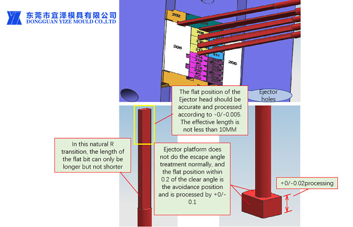
Schematic diagram of ejector assembly
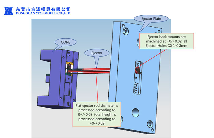
As high precision connector injection manufacture Yize Mould plastic injection molding parts for automobiles, optical fibers, mobile phones, cables, medical equipment, instrumentation, etc