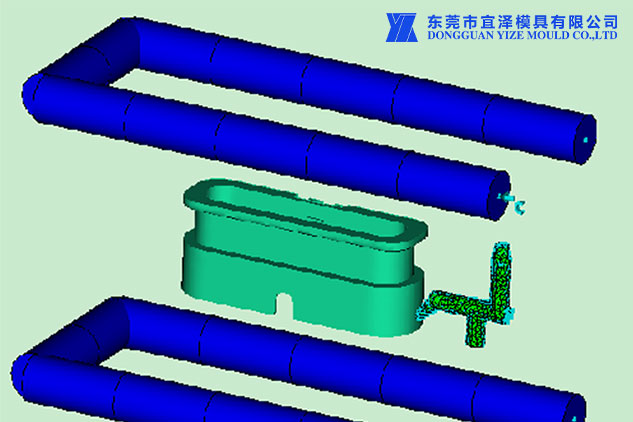
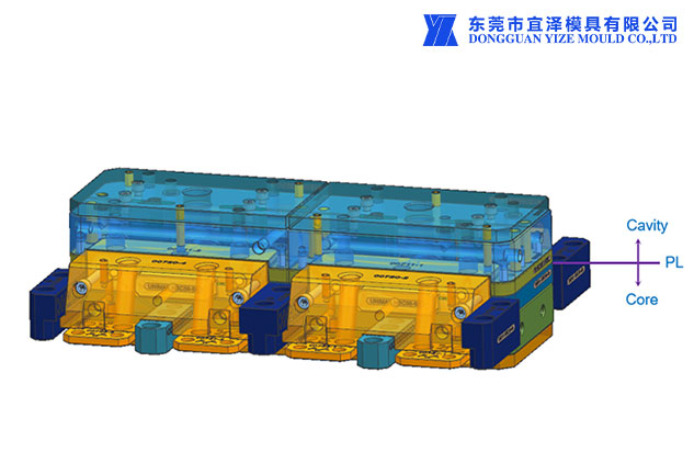
The basic situation of the PA6-GF15 plastic injection molding parts information is as follows:

Customer :TE
Part Name :PA6-GF15 plastic injection molding parts -- OUT HSG
Material :PA6-GF15(Ultramid® B3EG3)
Shrinkage :1.005
Mold Type (2/3plates) :2P Gate
Type /Hot runner supplier name :Hot Cold(Synventive)
Injection Machine :100T
Cavity quantity :4
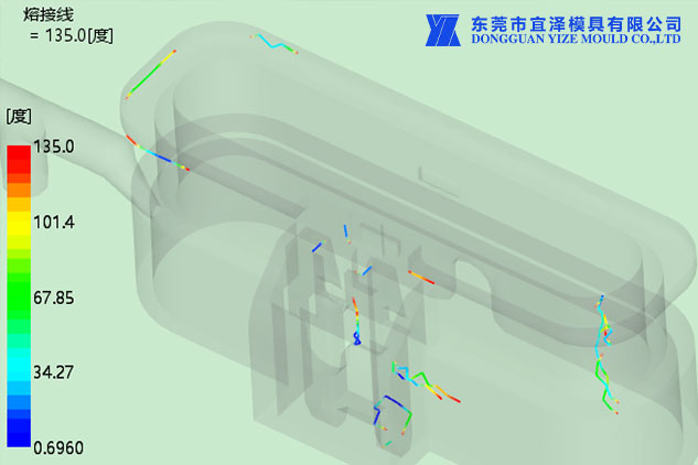
What we solved for the customer was the welding line on the PA6-GF15 plastic injection molding parts.

After analysis by our engineering team, there are two main points that need to be broken through:Poor mold exhaust and unreasonable structural design of plastic injection molding parts
1. Poor mold exhaust
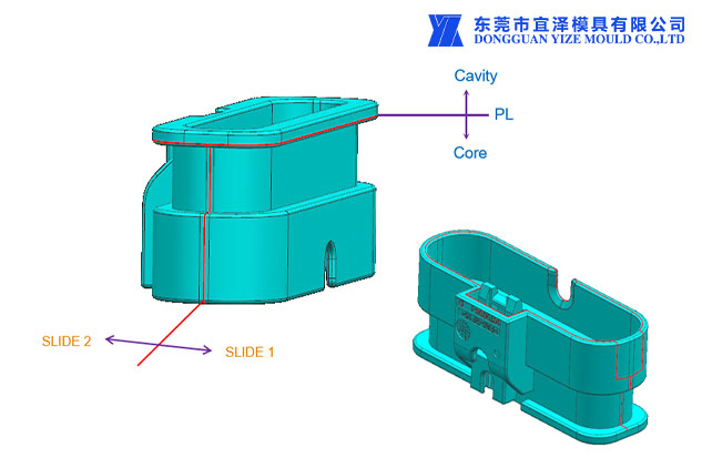
When the welding line of the molten material coincides with the clamping line or caulking of the mold, the air pressed by the multiple streams in the cavity can be discharged from the clamping gap or caulking;
(1) when the welding line does not coincide with the parting line or the caulking, and the vent holes are not set properly, the residual air in the mold cavity that is pressed by the flow material cannot be discharged, and the bubbles are strongly squeezed under high pressure, and the volume gradually becomes smaller.

(2) Since the molecular kinetic energy of the compressed air is converted into heat energy under high pressure, the temperature at the melting point is increased.
1) When the temperature is equal to or slightly higher than the decomposition temperature of the raw material, a yellow spot will appear at the melting point.
2) If the temperature is much higher than the decomposition temperature of the raw material, black spots will appear at the fusion point.
The main reason for such spots is due to poor mold exhaust, which is the carbonization point formed after the pyrolysis of the molten material.
So how to solve it?
First, check whether the mold exhaust hole is blocked by the solidified material or other objects of the melt, and whether there is foreign matter at the gate.
If the carbonization point still appears after the blockage is removed, the vent hole should be added at the mold collection point.
It is also possible to accelerate the confluence of materials by repositioning the gate or appropriately reducing the clamping force and increasing the exhaust clearance.
In terms of process operation, auxiliary measures such as reducing material temperature and mold temperature, shortening high-pressure injection time, and reducing injection pressure can also be taken.
2. The structural design of plastic injection molding parts is unreasonable
If the wall thickness of the plastic part is designed to be too thin, the thickness may vary greatly and there are too many inserts, which will cause poor welding.
When thin-walled parts are formed, defects are likely to occur because the melt solidifies too quickly, and the melt always converges at the thin wall to form a weld line during the filling process. The strength is reduced and the performance is affected.

How to avoid it for Precision plastic injection molding parts?
When designing the structure of the plastic part, it should be ensured that the thinnest part of the plastic part must be larger than the minimum wall thickness allowed during molding.
The use of inserts should be minimized to make the wall thickness of the plastic injection molding parts as consistent as possible.