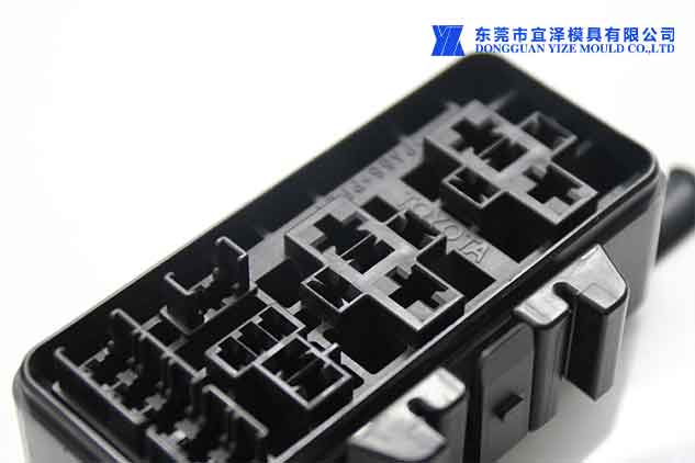
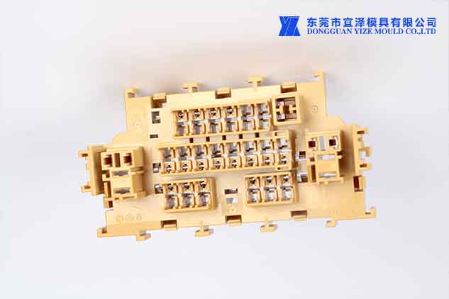
Connectors should not be unfamiliar to engineers. One of the very common components is the bridge between devices.
Decide which connector mold design you need
"Engineers tend to focus too much on designing the overall system and
In order to avoid such problems, relevant experts recommend that you should consider the connectors you will use early in the design, and then reserve design space for them, and the design will be built around them.
1. Signal
The key to optimizing high-speed connections is to ensure a minimal signal loss. Gathering a comprehensive understanding of these aspects allows users to understand the potential of high-speed connections.
2. PCB Termination Options
Designers must also consider the importance of PCB termination options. The robust connection of the press-fit terminals to the PCB is very secure, but it presents a challenge to the high-speed connections that users typically require, making high-density connectors difficult to route signals out of the PCB. Because termination styles typically require more layers in the PCB, this lengthens the signal's path, creates higher frequency discontinuities, and can inhibit signal speed.

3. Surface-mount terminal
Surface mount terminations are designed to be more sensitive to impedance matching, and designers can choose to make connections directly to the PCB. They are internal connections called "buried vias" in circuit boards and improve frequency response in a more efficient way than press-fit terminals. This method is more effective for high frequencies that experience losses in press-fit options, but they are hardly durable and often require additional mounting hardware to establish the secure connector that press-fit alternatives provide.
4. Connector mold design Paste hole terminal
Paste hole terminals contain features of the first two styles. The PIH style uses plated pinholes to solder the contacts into the PCB, similar to a press fit. The obvious difference between the two styles is the length of the PIH types and the holes they use, the pins are much shorter, allowing holes to be drilled to reduce excess

5. Connector mold design
Contacts within mating connectors must be considered when deciding which style to use in a system. Designers have a number of options when determining a contact configuration, and much like termination alternatives, each of these options has pros and cons. An edge mount connector is one such configuration, with a narrow spring-equipped stem that guides the connection to the PCB for greater continuity. However, shock and vibration pose a threat to the integrity of the connection under pressure, and safety may require additional reinforcement.
6. Crimp connection
Crimp connections are more commonly used for connections under stress that edge
Aa a Connector Mould company we has provided customers with a variety of standard connectors, and also has many years of customization experience, and can develop innovative design solutions according to customer needs.